
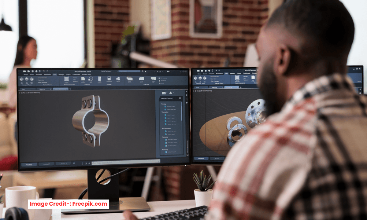
For decades, engineers and designers have been divided into two camps. On parametric modeling side, you have the disciples of precision and control, who believe that a model’s every dimension should be governed by rules and relationships in form of constrain. On Direct modeling side, you have the champions of speed and flexibility, who want to push and pull geometry like digital clay, unburdened by history trees and constraints. Some engineers support parametric modeling and some direct modeling as per my point of view both modeling method have their own pros and cons that we will discuss in this post. Parametric vs. Direct Modeling and which one to choose for CAD it is one of the most fundamental decisions any design team can make.
The choice isn’t about which one is “better” in absolute terms of course none of it absolute because it is totally depends upon many constrain like speed, time etc. it’s about which approach, or combination of approaches, best aligns with your workflow for example in very less span of time you have design your concept in that you parametric approach does not work because it will consume time a engineer will download relivent STEP file and directly edit it by tweaking face and feature and most of all CAD tool provide this feature. In FreeCAD which i use for my CAD projects which is Free and Open-Source have ability to edit STL file which you can watch in the below video. How I imported STL file and added my own feature rather than creating part from scratch.
The most progressive companies, engineer & hobbyist who develop their own product and modern CAD platforms now recognize that the future lies not in choosing one over the other, but in seamlessly integrating both based on project requirement. Let’s dive deep into what defines these methodologies, their strengths and weaknesses, and how you can chart the right course for your design process.
Deconstructing Parametric Modeling: The Architecture of Intent:
The engineers who believes in accuracy always support parametric modeling but what about speed when you have no time to start from scratch. Parametric modeling is a rule-based approach where geometry is driven by parameters, dimensions, and constraints and have parent child relationship if parents change child have to change. Parametric Modeling methodology built on capturing design intent.
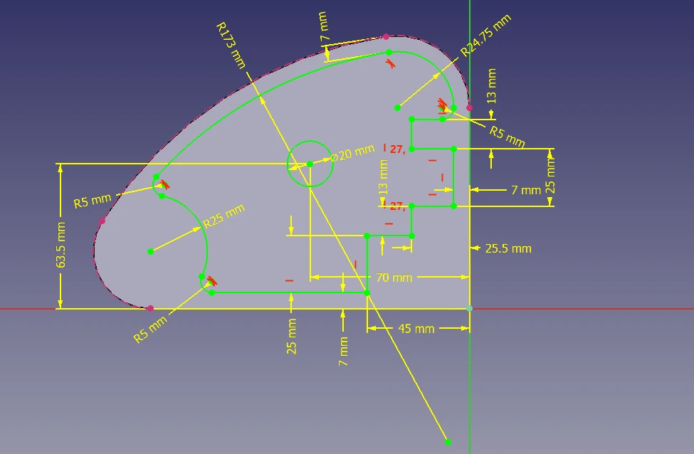
If you see above image sketch is fully constrain and have reference from parent feature which is radius once parent feature change child feature will have to adapt accordingly.
When you design a part parametrically, you aren’t just creating a shape; you are defining a set of relationships that dictate how that shape should behave when it changes and that might have external dependency as well like it’s parameter linked with spreadsheet where design data entered once spreadsheet parameter changes parametric part get updated. Parametric modeling recorded in a sequential “history tree” or “feature tree,” which lists every operation performed to create the model, from the initial sketch to the final fillet.
The Pillars of Parametric Design:
Parametric modeling rests on a few key pillars. First are parameters, which are the numeric values or variables that define the model—dimensions like length, width, or hole diameter. Then you have constraints, which are the geometric rules that govern the model’s shape, such as “parallel,” “perpendicular,” “tangent,” or “concentric”.
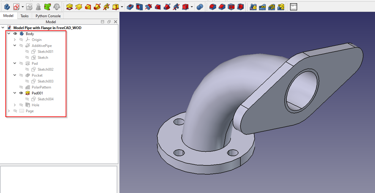
Finally, there’s the feature-based history, which captures the chronological order of operations. In above image you can see that how sweep profile is created and based on sweep profile flange is created when sweep profile change lets say internal diameter or outer diameter flange diameter also get updated. If you create a base extrusion, then add a hole, and then a fillet, that order is stored. This means a change to a parameter early in the history (like the base extrusion’s width) will automatically cascade through the model, updating the position of the hole and the fillet accordingly.
The Power of Discipline: Why Choose Parametric?
Parametric modeling shines in environments where precision, control, and systematic iteration are paramount. Its primary advantage is the ability to automate change. In a well-constructed parametric model, modifying a single dimension can ripple through an entire assembly, ensuring that related parts update flawlessly and consistently. This is invaluable for managing families of parts, where a core design is adapted into various sizes or configurations (e.g., a series of bolts or flanges). By changing a few key parameters, you can generate a new variant without rebuilding the model from scratch.
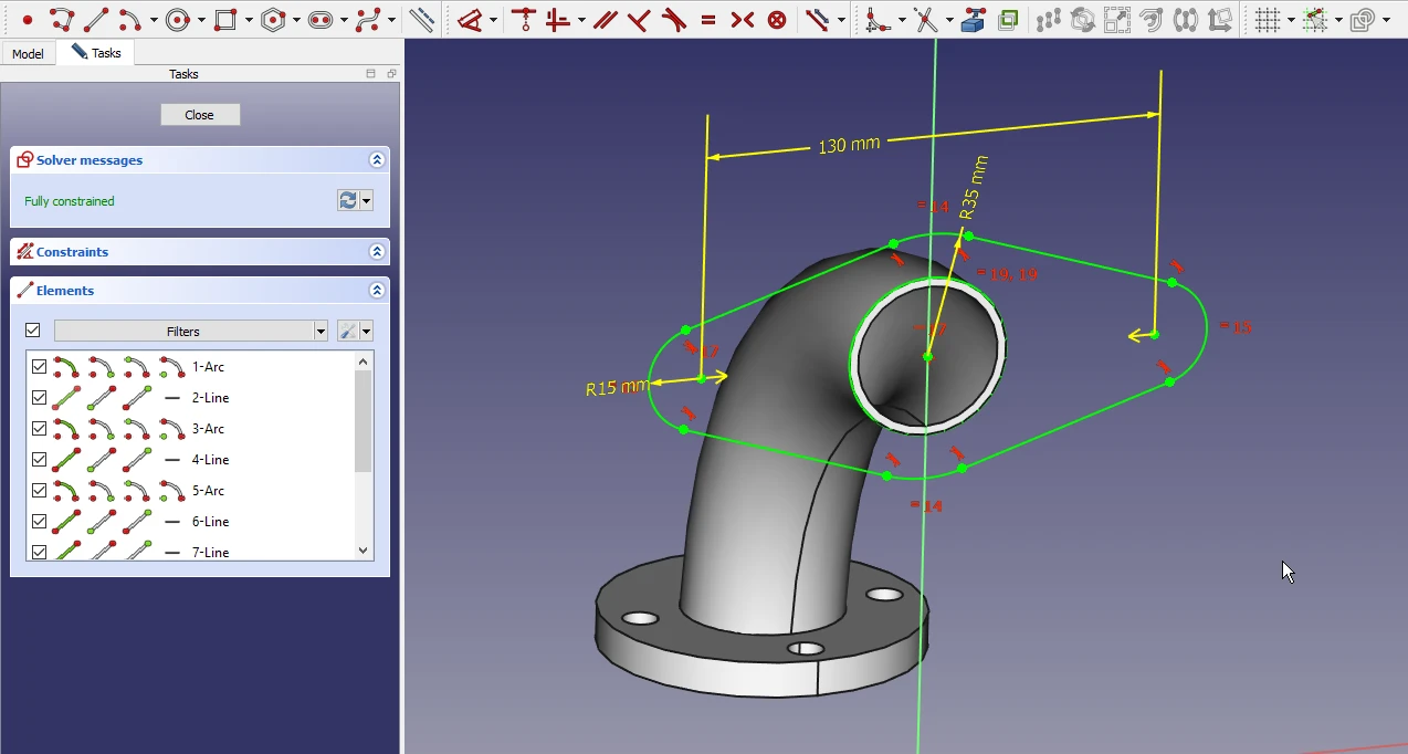
This approach also excels in complex assemblies with many interdependent parts, where maintaining relational intelligence is crucial for fit and function. The design history acts as a recipe, making it easier to understand, edit, and troubleshoot the model, especially for someone who didn’t create the original design. Furthermore, its rule-based nature provides excellent integration with downstream manufacturing processes (CAM, simulation), ensuring a seamless transition from design to production.
The Price of Precision: The Pitfalls of Parametric
However, this power comes with its own set of complexities. The very feature tree that provides control can become a “brittle” constraint if not managed carefully. Unexpected changes can cause rebuild errors, leading to the dreaded “constraint hell” where a model is under- or over-constrained and the designer must untangle a web of dependencies. Because of this, parametric modeling has a steeper learning curve. It requires a more strategic mindset to define parameters and structure a model in a way that is robust and adaptable.
Parametric design can also be overkill for early-stage concept development, where speed and exploration are more critical than precision. It forces a designer to commit to a feature history and constraints early on, which can slow down the rapid, iterative process of exploring a wide range of shapes and forms.
Embracing Direct Modeling: The Freedom of the Clay
Direct modeling takes a fundamentally different approach. Instead of defining a model through rules and a history tree, you interact directly with the geometry, using intuitive push, pull, and drag gestures to modify its shape. It’s often compared to working with a piece of virtual clay. You select a face, drag it, and it changes. It’s that simple. The lack of a history tree means there are no parent-child dependencies to manage—you can make changes anywhere, at any time, without worrying about breaking the model’s logic.
The Hallmarks of Agility: The Direct Approach:
The primary advantage of direct modeling is its unparalleled speed and flexibility. It is the ideal tool for concept design, where the goal is to generate and iterate on ideas rapidly. You can think fast and model fast, unburdened by constraints.
Direct modeling is also a lifesaver when dealing with “dumb” or “dumb” solid data. In the engineering world, this refers to imported 3D models (e.g., from a STEP or IGES file) that lack a parametric history. With direct modeling tools, you can easily open such files and immediately edit the geometry—moving a face, resizing a hole, or modifying a feature—without needing to understand how the model was originally built. This makes it invaluable for reusing and repurposing legacy data. Its low barrier to entry makes it easier for new users to pick up and for casual users to make quick edits.
The Inherent Trade-off: The Limits of Direct Freedom:
The flexibility of direct modeling comes at the cost of capturing design intent. Because you aren’t defining relationships and parameters, the model doesn’t “know” why a hole is a certain distance from an edge. A direct edit is just a geometric change; it doesn’t carry any logic. This can make managing complex models or creating systematic design variations challenging. Without the underlying rules of a parametric history, significant changes to a direct model can be tedious, requiring manual, “one-off” edits to every affected area. While it excels at speed for one-off modifications, the lack of a history means you lose the ability to track granular, edit-by-edit changes, making it harder to review or revert specific modifications.
The Hybrid Renaissance: The Best of Both Worlds
The modern CAD industry, led by companies like Siemens, PTC, and Autodesk, recognizes that the “parametric vs. direct” debate is somewhat outdated. The future is hybrid, or what Siemens calls Synchronous Technology. This approach allows designers to move fluidly between parametric and direct modeling within a single environment and on the same model. Tools like PTC Creo and Autodesk Fusion 360 are prime examples of this trend, enabling users to leverage the speed and flexibility of direct edits on an existing parametric model.
Hybrid workflows provide a powerful solution to the classic trade-offs:
- Late-Stage Changes: You can make a radical, unexpected change late in the design process using direct modeling tools, without risking the integrity of the entire parametric feature tree. This “break the rules” ability is critical for meeting tight deadlines.
- Concept to Production: Start a design in a freeform, direct modeling environment to explore ideas. As the concept matures and requirements solidify, you can introduce parameters and constraints, effectively building a history around the geometry to prepare it for production.
- Collaboration & Legacy Data: When receiving CAD data from a supplier or client that lacks a history, you can directly edit and modify it as if it were native. The software can even infer parametric relationships (like symmetry or patterns) from direct edits, adding them to the model’s history for future control.
Conclusion: Which Side Are You On?
Choosing between parametric and direct modeling is less about picking a side and more about understanding the context of your work. The right answer often involves both.
Parametric modeling is your tool of choice when:
- You are designing production-ready parts and complex assemblies.
- The design will be part of a family of parts, with multiple variants.
- You need predictable, automated updates across large assemblies.
- Precision, consistency, and stringent manufacturing requirements are paramount.
Direct modeling is your go-to method when:
- You are in the early stages of concept design and exploration.
- You need to make quick, one-off changes or repairs to imported legacy data.
- Speed, agility, and a low learning curve are the priority.
The hybrid approach is the modern best practice when:
- Your workflow demands flexibility and precision at different stages.
- You work with data from multiple sources (different CAD systems, legacy models).
- You want a CAD platform that empowers your entire team, from industrial designers to mechanical engineers, to work together effectively.
Look at the successful companies profiled by industry leaders like PTC: automotive teams at KTM rely on hybrid workflows to integrate the best of engineering at every release, enabling continuous innovation. This is the true promise of modern CAD—not forcing a choice between two competing philosophies, but providing a unified toolset that empowers the designer to choose the right tool for the job, at the right time.
“Thank you for reading! If you found this article insightful and valuable, consider sharing it with your friends and followers on social media. Your share can help others discover this content too. Let’s spread knowledge together. Your support is greatly appreciated!”
