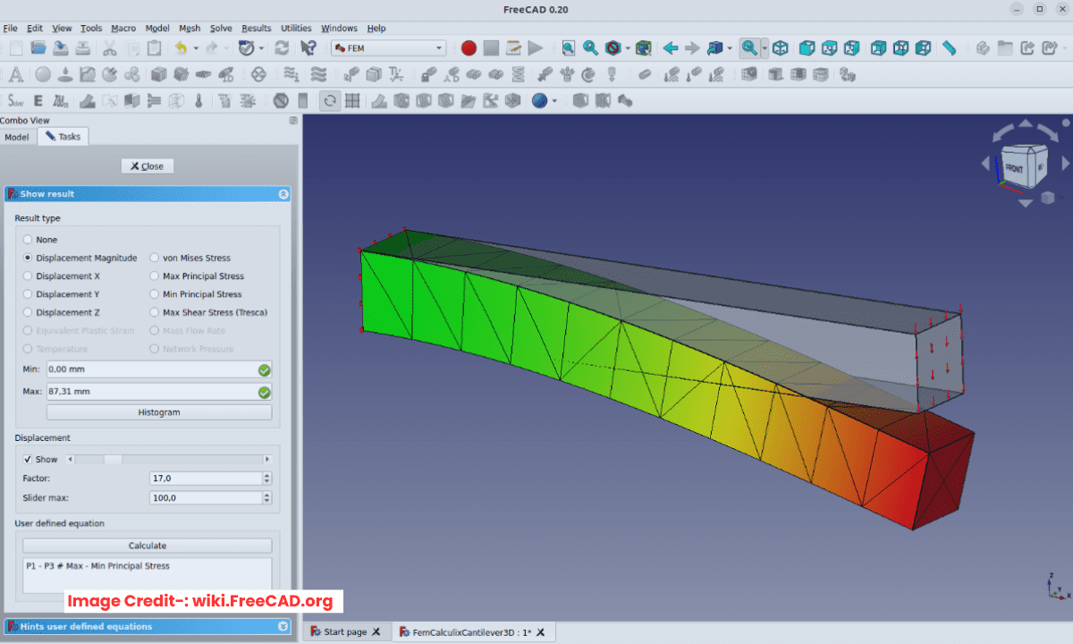
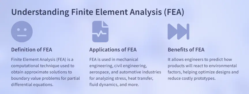
FEA is a computational method for predicting how a physical part or assembly behaves under real-world forces, vibration, heat, and other conditions to reduce the prototype cost. FEA works by breaking down a complex, real-world object into a large number (thousands or millions) of small, simple pieces called “elements.” These elements are connected at specific points called “nodes.” This collection of elements and nodes is called a “mesh.”
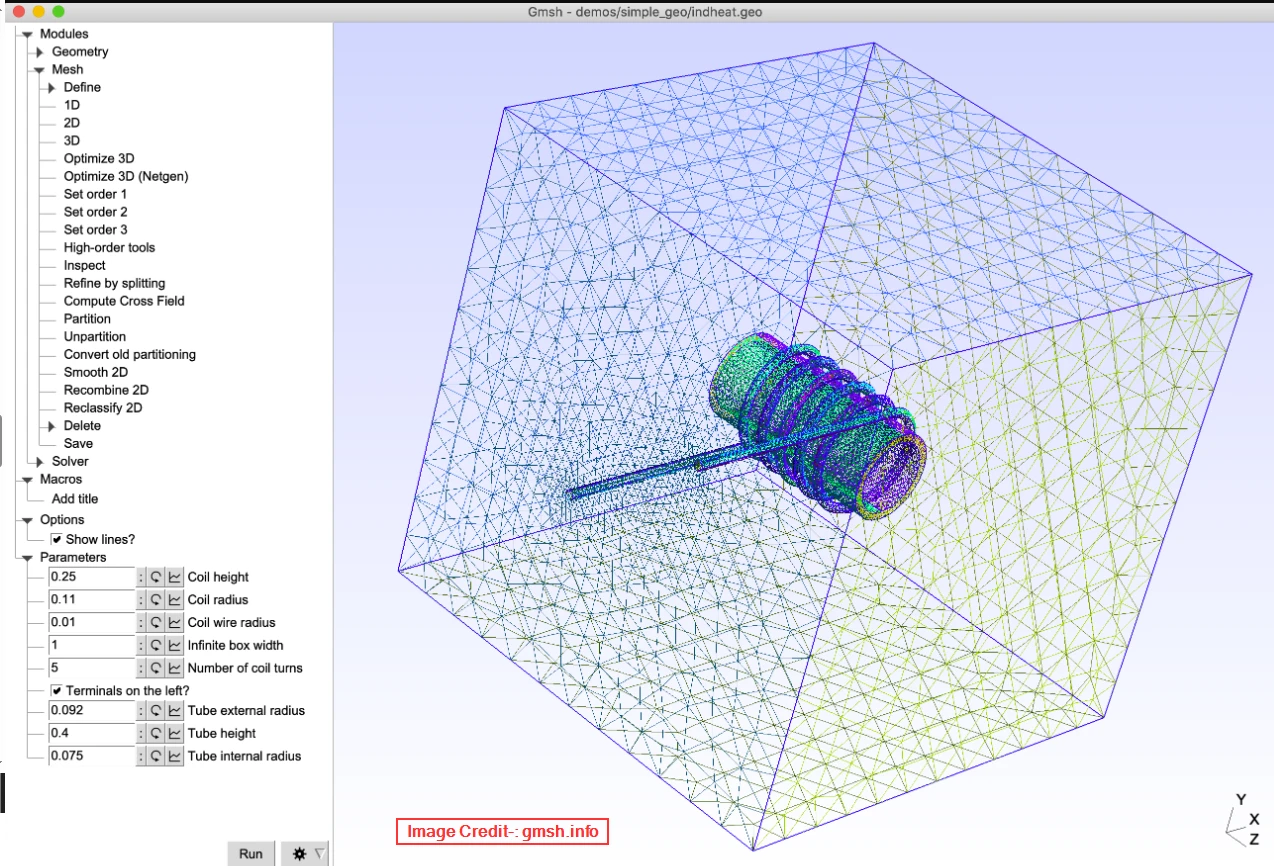
I learned Finite Element Analysis using FreeCAD FEM Workbench. I love FreeCAD a lot because it is single CAD tool which fulfill all need of a Mechanical design engineer. When it come to meshing for FEA use Gmsh and it give robust result. I did one FEA analysis where I validated manual hand calculation with FEA analysis.
The Process: How it Works-:
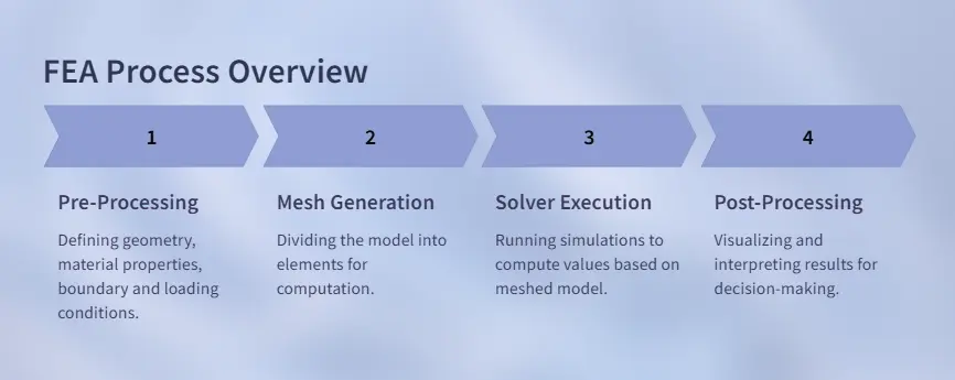
1. Pre-Processing (The Setup):
-
-
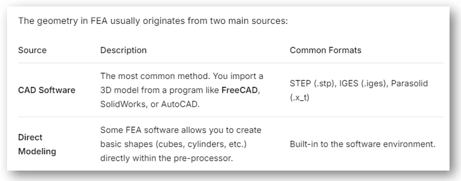
Geometry: In FEA, the geometry is the digital representation of your physical part. It’s the shape you’re going to analyze—whether it’s a simple bracket, a complex engine block, or an entire assembly.
The quality and preparation of this geometry directly determine how accurate, fast, and reliable your final results will be. The solver will run its calculations on this virtual shape, so the closer it matches your real-world part, the better your predictions will be.
-
-
-
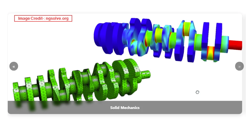
Meshing: Meshing is most importance process of FEA result there are the special software for meshing like Altair HyperMesh which provides high fidelity meshing. In meshing process software divides the geometry into the mesh of small elements. A finer mesh yields more accurate results but requires more computational power.
-
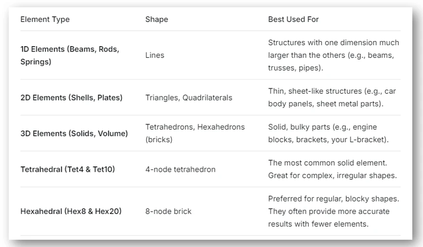
In FreeCAD FEM Workbench you will get two meshing option First in Gmsh which provides advanced tetrahedral meshing with control over element size and mesh density, ideal for complex simulations and second is Netgen which provides robust mesher tool often used for 3D volumetric meshing. The type of element you choose is one of the most important decisions in meshing. It depends on your geometry and the type of analysis you’re performing.
-
-
Material Properties: You define what the part is made of (e.g., steel, aluminum, plastic) by assigning properties like Young’s Modulus and Poisson’s ratio.
-
Boundary Conditions & Loads: You apply the real-world constraints (e.g., fixed faces, pins) and the forces, pressures, or temperatures that act on the part.
-
2. Solution (The Calculation):
The FEA software solves a giant set of algebraic equations for each node, based on the principles of physics and mechanics of materials. This process calculates primary quantities like displacement at each node.
FEA software takes the partial differential equations that govern physics (like the equations of elasticity) and converts them into a set of algebraic equations using a method called the Finite Element Method. FEA software assembles equations for every single node in the mesh, resulting in a massive system of equations.
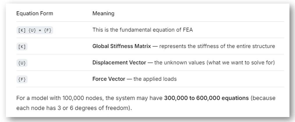
The whole summery is FEA software convert physical problem into math the physical problem may be Stress, Vibration or thermal analysis and it result giant system of equation for all nodes. For a model with 100,000 nodes, the system may have 300,000 to 600,000 equations (because each node has 3 or 6 degrees of freedom).
3. Post-Processing (The Results):
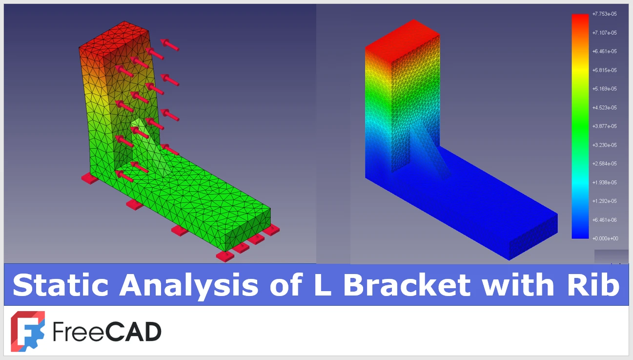
Post-processing is the final and one of the most important phases of a Finite Element Analysis (FEA) . It’s the step where you take the raw numerical results (the solved equations) and turn them into meaningful, visual information that engineers can interpret to make design decisions. This is where you finally get to “see” how your design behaves.
-
-
Stress : The internal forces within the material. Displays where the maximum stress occurs.)
-
Strain : The amount of deformation relative to the original size.
-
Displacement : How much the model moves or deforms under the load.
-
Reaction Forces : Forces required at supports to keep the model in equilibrium.
-
Modal Frequencies : Natural frequencies and mode shapes of the structure (in modal analysis).
- Temperature Distribution : Heat flow and thermal gradients (in thermal analysis).
-
Also Read-:
- Creo+ Powerful CAD in The Cloud
- Creaform Releases Scan-to-CAD Pro for Advanced 3D Data Conversion
- JETCAM Introduces a Free Tool for Viewing CAD Files
Key Applications in Mechanical Engineering-:
-
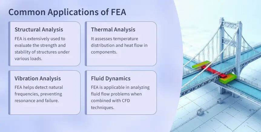
Structural Analysis: Predicting stresses and deflections to ensure a design is strong and stiff enough.
-
Modal Analysis: Determining the natural frequencies and mode shapes of a component to avoid resonance.
-
Thermal Analysis: Calculating temperature distribution and heat flow.
-
Fatigue Analysis: Estimating the product’s life under cyclic loading.
In essence, FEA is a powerful virtual testing tool that allows engineers to optimize designs, reduce physical prototyping, and ensure safety and reliability before a single part is ever manufactured.
Finite Element Analysis is a computational method used by engineers to predict how a product will react to real-world forces, such as heat, vibration, and stress. Think of it as a virtual stress-testing simulator.

The Core Concept: Breaking Down the Complex-:
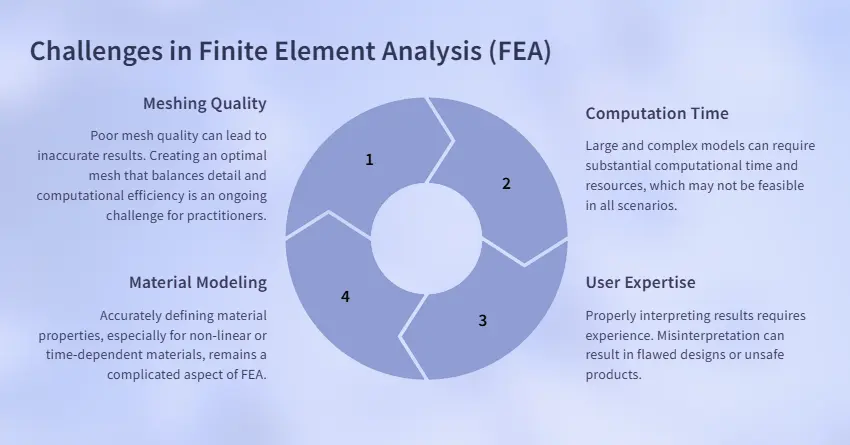
The core idea is simple: you take a complex geometry and break it down into a finite number of small, simple pieces (called “elements”). These elements are connected at specific points (“nodes”). It’s much easier to solve the physics for these simple pieces and then combine the results to understand the behavior of the entire, complex object. This mesh of elements and nodes is called a “mesh.”
Also Read-:
- Creo+ Powerful CAD in The Cloud
- Propel and Bild Simplify CAD Integration with Cloud-Based PLM–PDM Connection
- JETCAM Introduces a Free Tool for Viewing CAD Files
A Simple FEA Analogy:
Imagine predicting the sag of a fishing net. Analyzing the entire net at once is difficult. But if you analyze the force on each small knot (node) and the stretch of each piece of string (element), you can assemble the data to see how the entire net deforms. FEA does this for solid objects.
The Basic FEA Workflow:
1. Pre-Processing (The Setup):
-
-
Geometry: You create or import a 3D model of your part.
-
Meshing: You divide the model into the small elements, creating the mesh. A finer mesh in critical areas gives more accurate results but takes longer to compute.
-
Material Properties: You define what the part is made of (e.g., steel, aluminum, plastic) by assigning properties like density and strength.
-
Boundaries & Loads: You apply the real-world conditions: How is it held? (e.g., a bolt hole is fixed). What forces are acting on it? (e.g., a 100 lb weight).
-
2. Solving (The Black Box):
-
-
The FEA software (like ANSYS, Abaqus, or SimScale) assembles and solves a gigantic set of mathematical equations for every single node. This is the number-crunching phase, handled by the computer.
-
3. Post-Processing (The Results):
-
-
You visualize the results using color-coded plots. Common results include:
-
Stress: Where is the part most likely to fail?
-
Strain: How much is it stretching or compressing?
-
Displacement: How much does it bend or move from its original shape?
-
-
Also Read-:
- Open-Source CAD Software for Linux Operating System
- FreeCAD Integration with KiCAD
- How AI in CAD Market Transforming Growth
Why Use FEA?
-
Reduce Physical Prototyping: Test and refine designs digitally, saving immense time and cost.
-
Identify Weak Spots: Find problem areas before manufacturing.
-
Optimize Designs: Make parts lighter, stronger, and more efficient.
A Word of Caution for Beginners:
FEA is a powerful tool, but it follows the principle of “Garbage In, Garbage Out.” A beautiful color plot is meaningless if the initial setup (loads, constraints, material) is wrong. Understanding the underlying physics is crucial to interpreting results correctly. Start with simple models and validate your results with hand calculations or known data.
“Thank you for reading! If you found this article insightful and valuable, consider sharing it with your friends and followers on social media. Your share can help others discover this content too. Let’s spread knowledge together. Your support is greatly appreciated!”